


Published on Apr 02, 2024
The digital data bus MILSTD 1553B was designed in early 1970's to replace analog point to point wire bundles between electronic instrumentations. The MILSTD 1553B has four main elements.
1. Bus controller to manage information flow.
2. Remote terminals to interface one or more subsistence.
3. Bus monitor for data bus monitoring.
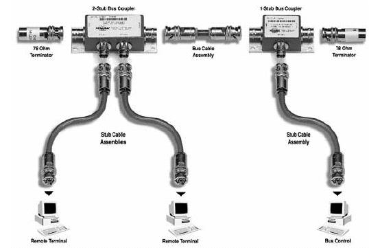
4. Data bus components. Including bus couplers, cabling, terminators and connectors.
This is a differential serial bus used in military and space equipments comprised of multiple redundant bus connection and communicates at one MBps. Bus has single active bus control and up to 31 remote terminals. Data transfer contain up to 16 bit data word.
MILSTD 1553 is military standard that defines the electrical and protocol characteristic for data bus. A data bus is used to provide a medium for exchange of data between various systems. It is similar to LAN in personal computers and office automation industry. A data transmission medium which would allow all systems and subsistence to share a common set of wires was needed. So MILSTD 1553 standard redefines TDM as the transmission of data from several signal sources through one communication system with different signal samples staggered in time to form a composite pulse train.
In 1968 SAE a technical body of military and industrial members estd a subcommittee to define a serial data bus to meet the needs of military avionics community under the project name A 2 - K. This subcommittee developed first draft in 1970. In 1973 MILSTD 1553 was released through F - 16 fighter plane.
Then MILSTD 1553 A was released in 1975 through air forces F 16 and army's attack helicopter AH - 64 A Apache. 1553 B was released in 1978. The SAE decided to freeze the standard to allow the component manufacturers to develop real world 1553 products.
Applied to satellites as well as in space shuttles. Used in large transporters, aerial refuelers and bombers, tactic fighters and helicopters. It is even contained in missiles and may act as primary interface between aircraft and missiles. Navy has applied this data bus to surface and subsurface applications. Army has put 1553 in to tanks.
Commercial applications have applied standard to systems like manufacturing production lines and BART (bay area rapid transport). UK has issued standard 0018 P and NATO has published STANAG 3838 AVS both in accordance to 1553 B. MILSTD 1760 A the air craft store interconnect has 1553 B embedded in it.
Comprises of
1. Transmission media .
2. Remote terminals
3. Bus controllers
4. Bus monitor
Twisted shielded where of transmission line consisting of main bus and number of stubs. Main data bus is terminated with a resistance equal to cable’s characteristic impedance. This termination make the databus behave like an infinite transmission line. Stubs are added to main bus to connect terminals and provide local loads and produce impedance mismatch .
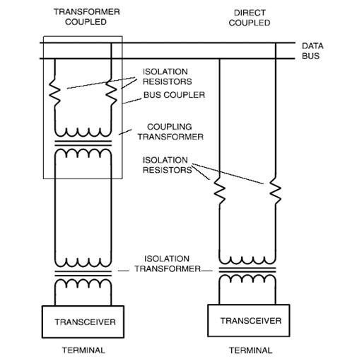
It is highly recommended that bus be modeled and tested to ensure its operation and performance characteristics. There are two methods for terminals to be connected to mainbus.
1. Direct coupled (one feet)
2. Transformer coupled (twenty feet)
The remote terminals comprises of electronics necessary to transfer data between databus and subsystem. A remote terminal is now embedded in todays subsystems. Remote terminal typically consist of transceiver, an encoder decoder, a protocol controller, a memory and a subsystem interface. In a modern black box containing a processor the subsystem interface may consist of buffers.
A remote terminal must be more than a data formatter. It must be capable of receiving and decoding commands from BC and respond accordingly. It must also be capable of buffering a message worth of data, detecting transmission errors and performing validation test upon the data.
A remote terminal must follow the protocol defined by the standard. It can only respond to commands received from BC.
BC is responsible for directing flow of data on databus. The BC is the only one allowed to issue commands on to databus. The complexity of electronics associated with the BC is a function of subsystem interface, the amount of error management and processing to be performed, and architecture of the BC.
There are three types of BC architecture.
1. Word controller
2. Message controller
3. Frame controller
Bus monitor (BM) is a terminal that listens or monitors the exchange of data on databus. The standard strictly defines how bus monitors may be used stating that the information obtained by a BM be used for offline application or to provide backup the BC. BM is a passive device that doesn’t transmit a status word and there for cannot report on status of data transferred. BM is categorized in to two.
1. A recorder for testing (recording device like magnetic tape)
2. A terminal functioning as backup BC (computer)
| Are you interested in this topic.Then mail to us immediately to get the full report.
email :- contactv2@gmail.com |
